Index:
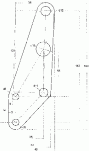
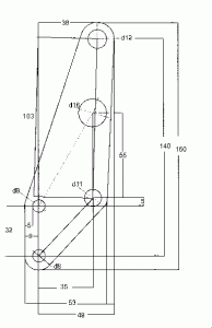
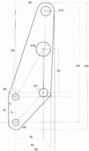
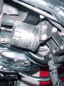
Oil bracket for A65 machines
BSA Bearings
Oil bracket for A65 machines
Diagrams provided to guide fabrication of bracket to hold spin-on oil filter.


BSA Bearings
NOTE: This is an early draft for review purposes only. Take everything with a large grain of salt.
This BSA bearing quick reference is inspired by the Norton Owners Club (NSW) Commando bearing guide. While later BSA parts books and manuals provided much more information regarding the bearings fitted than the Norton equivalents, it is still somewhat fiddly to work through the parts books and / or factory workshop manuals to find what bearings are required.
BSA, like most mototcycle manufacturers, fitted a number of different bearing types to the models over the years. Plain bushes and slipper shells tend to be specialist items, but the various ball and roller bearings were off-the-shelf components which should still be available from industrial bearing suppliers.
The aim of this guide is to eventually compile a full list of off-the-shelf bearings and oil seals, both original fitment and modern cross-references) for all post-War BSA models.
Please note that this is (and probably will remain) a work in progress. We try our best, but don’t guarantee to get it all correct. Suggestions and corrections will be incorporated as time permits.
Information for this guide has been obtained from BSA manuals, bearing cross-references, Ruper Ratio’s Unit Singles book and contributions from other BSA enthusiasts
General bearing stuff
Bearings come in 4 basic forms
- bushes
- slipper shells
- balls
- rollers
bushes are generally machined from sintered bronze, and can be made by any machinist with access to a lathe and supplies of bearing stock. Unless you have ready (cheap) access to a lathe, expertise and sintered bronze rod it is usually best to buy bushes ready-made from a motorcycle parts supplier. Bushes tend to be used in low(er) friction / limited space locations with a reasonable oil supply. Most camshaft and gear pinions run on bushes, as do many gearbox layshafts. Gudgeon pins (wrist pins for the Americans) also usually run on bushes. Bushes are also used for light loads in applications with limited lubrication, such as rocker shafts. Bushes have a high load-carrying capacity
slipper shells are thin steel shells with a lining of softer metal (usually babbit, white metal or aluminium alloy) for the friction surface. The bearing should have no metal-to-metal contact, but relies on an oil film between the disparate metal surfaces. The usual application is for connecting rod big-end shells running on one-piece crankshafts. The infamous BSA twin “timing side bush” is actually a cylindrical slipper shell. Used slipper shells can be re-metalled by specialists, but it is usually best to buy new replacements from a motorcycle parts supplier. Slippers have a high load-carrying capacity and require good high-pressure oil supply
Ball bearings come in 2 forms, loose or caged. Loose balls are generally only used in steering head races or (very early) wheel bearings. The races (cup and cone) are specialist items, but the balls should be avaiilable from bearing suppliers. The ball bearings used most often are ball journal bearings, which come complete with the inner and outer races (cup and cone). The balls are held in place by a cage, which may be made from steel, brass or polyamide. Brass cages tend to be best for engine and gearbox use. Some applications also have a cage without the cup and cone. The BSA 6-spring clutch used a pair o open ball cages.
Ball bearings have a much lower load-carrying capacity than bushes or rollers, but can carry axial loads as well as radial loads. This makes them useful in situations where a shaft has to be held in place with minimal sideways movement. Ball bearings can work in poorly lubricated environments, and sealed pre-lubricated ball bearings are to be preferred ito unsealed versions n exposed applications such as wheel bearings.
Roller bearings can come loose or caged. Rollers also come in various aspect ratios. Long thin rollers are referred to as needle rollers. Rollers can also have various degrees of radius at the ends, ranging from very sharp to rounded.
Roller bearing assemblies are either parallel or taper. Parallel rollers have a very good radial load-carrying capacity but are quite poor for axial loads. Tapered rollers have good radial and axial load-carrying capacity – in *one* direction. They tend to be used in pairs at both ends of a shaft (eg the steering heads of the oil-in-frame twins, car wheel bearings) and need a slight pre-load to stop them chattering. Needle rollers come in parallel or radial configurations. radial needle rollers are used as thrust bearings. They have a very high axial load capacity, but next to no radial capacity.
Roller bearings can work with light lubrication. Sealed pre-lubricated rollers are to be preferred to unsealed rollers in exposed applications
BSA engine and gearbox bearing units generally seem to be C3 clearance (larger clearance than standard). Brass cages are preferred. Brass is comparatively soft, so causes less damage than steel if the cage falls apart. It handles heat better than polyamide so brass-caged bearings can be re-used after removal by heating.
What do all the markings mean?
Bearing assemblies almost always have numbers on one edge of the outer race, inner race or both races . This number should represent the base bearing assembly type, with one or more modifiers. The 1971 BSA twins workshop manual has a section on the modifier markings. Siimilar sheets should be available from bearing companies.
The main modifers of interest for British bikes are:
| C3 or 000 | larger radial internal clearance |
| M | machined brass cage located on the rolling elements |
| RS | one “rubber” seal |
| -2RS | two “rubber” seals |
| TBH | phenolic cage |
| TNH | polyamide cage located on rolling elements |
| Y | pressed brass cage |
| Z | one metal shield |
| -2Z | two metal shields |
Imperial and metric dimension
Items manufactured to Imperial dimensions (inches, feet, yards, perches, chains, etc) were usually dimensioned in multiples of 1/64 of an inch rather then hundredths. The dimensions normally come out neatly in eighths or quarters, with the very occasional sixteenth, thirty-second or sixty-fourth. Bear this in mind when measuring bearings with calipers or micrometers calibrated in decimal fractions of an inch. Once upon a time, calipers used to be graduated in sixty-fourths.
Items manufactured to metric dimensions tend to be made in decimal fractions of a millimetre
BSA Unit Singles C15, C25 B25, B40, B44, B50
Engine
| Crankshaft | ||||
| Drive side outer | ||||
| 1971 – 1973 (B50) | ball journal | 1 | ||
| Hoffman | LS9 | |||
| Drive side inner | ||||
| 1959 – 1973 | roller journal | 1 | ||
| Hoffman | R325L | |||
| Timing Side | ||||
| 1959 – 1970 | ball journal | 1 | ||
| Hoffman | 325 | |||
| 1971 – 1973 (B50) | roller journal | 1 | ||
| Hoffman | R325L |
Gearbox
| Mainshaft | ||||
| Drive side | ||||
| 1968 – 1973 | ball journal | 1 | ||
| Hoffman | 130 | |||
| Timing side | ||||
| 1963 – 1973 (non-distributor models) | ball journal | 1 | ||
| Hoffman | LS7 (L27?) | |||
| Layshaft | ||||
| Drive side | ||||
| 1968 – 1973 | needle roller | 1 | ||
| Torrington | B108 | |||
| Timing side (kickstart spindle) | ||||
| 1968 – 1973 | needle roller | 1 | ||
| Torrington | B108 | |||
| Clutch | ||||
| Centre | 3/16″ x 3/16″ | loose roller | 25 |
Wheels
| Front | ||||
| Single-sided brake | ||||
| 1962 – 1969 | 7/8″ x 2″ x 9/16″? | ball journal | 2 | |
| Hoffman? | LS90R | |||
| single-sided brake | ||||
| 1968 – 1970 | ball journal | 2 | ||
| Hoffman? | LS9RS | |||
| conical hub | ||||
| 1971 – 1972 | 20mm x 47mm x 14mm | ball journal | 2 | |
| Hoffman | 120 | |||
| Rear | ||||
| QD “crinkle hub” | ||||
| 196? – 1970 (drum) | ball journal | 1 | ||
| Hoffman | LS9 | |||
| hub | ball journal | 2 | ||
| Hoffman | LS9RS | |||
| bolt-on drum | ||||
| 196? – 1970 | 7/8″ x 2″ x 9/16″? | ball journal | 2 | |
| Hoffman? | LS90RS? | |||
| full width hub | ||||
| 1962 – 1965 | ball journal | |||
| conical hub | ||||
| 1971 – 1972 | 20mm x 47mm x 14mm | ball journal | 2 | |
| Hoffman | 120 |
Front end
| Steering head | 1962 – 1970 | 1/4″? | loose ball | 40 |
| 1971 – 1972 | taper roller | 2 | ||
| Timken | LM.11949L |
Rear end
| Swinging arm | ||||
| 1971 – 1973 | needle roller | 2 | ||
| Torrington | B1616 |
BSA Pre-Unit Twins A7 / A10
Wheels
| Rear | ||||
| QD “crinkle hub” | ||||
| 195? – 1963 (drum) | ball journal | 1 | ||
| Hoffman | LS9 | |||
| hub | ball journal | 2 | ||
| Hoffman | LS9 |
BSA Unit Twins A50 / A65 / A70
Engine
| Crankshaft | ||||
| Drive side | ||||
| 1962 – 1965 | ||||
| 1966 – 1972 | 1.125″ x 2.812″ x .812″ (1 1/8″ x 2 13/16″ x 13/16″ ?) |
roller journal | 1 | |
| Hoffman | RM.11L | |||
| R & M | MRJA 1 1/8 | |||
| RHP | MRJA1.1/8J | |||
| only appears to be available in original RHP |
Gearbox
| Mainshaft | |||||
| Drive side | |||||
| 1962 – 1972 | 1 1/4″ x 2 1/2″ x 5/8″ | ball journal | 1 | ||
| Hoffman | 9554/V4 | ||||
| Skefco | RLS.9 1 1/4 | ||||
|
|||||
| Timing side | |||||
| 1962 – 1972 | 3/4″ x 1 7/8″ x 9/16″ | ball journal | 1 | ||
| Hoffman | L.38 | ||||
| Skefco | RLS.6 | ||||
| R & M | LJ 3/4 | ||||
| Layshaft | RLS6-2RS (remove inner rubber shield) |
||||
| Drive side | |||||
| 1962 – 1972 | 3/4″ x 3/4″ | needle roller | 1 | ||
| Torrington | M.12121-OH | ||||
| CS1212 | |||||
| Timing side | |||||
| 1962 – 1972 | 3/4″ x 3/4″ | needle roller | 1 | ||
| Torrington | B.1212-OH | ||||
| B1212OH | |||||
| Clutch | |||||
| Centre | 1/4″ x 1/4″ | loose roller | 20 |
Wheels
| Front | ||||
| Single-sided brake | ||||
| 1962 – 1969 | 7/8″ x 2″ x 9/16″ | ball journal | 2 | |
| Hoffman | LS90R | |||
| full-width brake | ||||
| 1968 – 1970 | 20mm x 47mm x 14mm | ball journal | 2 | |
| Hoffman | 120 | |||
| conical hub | ||||
| 1971 – 1972 | 20mm x 47mm x 14mm | ball journal | 2 | |
| Hoffman | 120 | |||
| Rear | ||||
| QD “crinkle hub” | ||||
| 1962 – 1970 | ||||
| bolt-on drum | ||||
| 1962 – 1970 | 7/8″ x 2″ x 9/16″ | ball journal | 2 | |
| Hoffman | LS90RS? | |||
| full width hub | ||||
| 1962 – 1965 | ball journal | |||
| conical hub | ||||
| 1971 – 1972 | 20mm x 47mm x 14mm | ball journal | 2 | |
| Hoffman | 120 |
Front end
| Steering head | 1962 – 1970 | 1/4″ | loose ball | 40 |
| 1971 – 1972 | taper roller | 2 | ||
| Timken | LM.11949L |
BSA / Triumph triples A75 Rocket Three, X75 Hurricane, T150/T160 Trident
Engine
| Crankshaft | ||||
| Drive side | ||||
| 1968 – 1977 | ball journal | 1 | ||
| Hoffman | LS.11 | |||
| Timing side | ||||
| 1968 – 1977 | roller journal | 1 | ||
| Hoffman | R.125 | |||
| Timing gear | ||||
| needle roller | 1 | |||
| Torrington | B.1110 |
Gearbox
| Mainshaft | ||||
| Drive side | 1 | |||
| 1968 – 1977 | ||||
| Timing side | 1 | |||
| 1968 – 1977 | ||||
| Layshaft | ||||
| Drive side | ||||
| 1968 – 1977 | 1 | |||
| Timing side | ||||
| 1968 – 1977 | 1 | |||
| Clutch | ||||
| shaft | ||||
| 1968 – 1977? | needle roller | |||
| INA | SC.228 | 1 | ||
| thrust race | ||||
| 1968 – 1977? | radial roller | 1 | ||
| Torrington | NTA.2233 | |||
| lever | ball journal | |||
| 1968 – 1977? | ||||
| Hoffman | S5 |
Wheels
| Front | ||||
| full-width brake | ||||
| 1968 – 1970 | 20mm x 47mm x 14mm | ball journal | 2 | |
| Hoffman | 120 | |||
| conical hub | ||||
| 1971 – 1973 | 20mm x 47mm x 14mm | ball journal | 2 | |
| Hoffman | 120 | |||
| disc brake | ||||
| 1973 – 1977 | 2 | |||
| Rear | ||||
| bolt-on drum | ||||
| 1968 – 1970 | 20 x 47 x 14 mm | ball journal | 2 | |
| Hoffman | 120 | |||
| conical hub | ||||
| 1971 – 1975 | 20 x 47 x 14 mm | ball journal | 2 | |
| Hoffman | 120 | |||
| disc brake | ||||
| 1975 – 1977 | 2 |
Steering head
| 1968 – 1977? | 1/4″ | loose ball | 40 |
What goes with which?
The last BSAs were manufactured in 1973, so many of the bearings will be obsolete.
Most bearing shops will have excellent cross-reference charts, but it might prove useful to have some initial alternatives
Here goes…
| Original | Alternative |
| Manufacturer | Bearing | Manufacturer | Bearing |
| Hoffman | LS90R | ||
| Hoffman | LS9 | ||
| SKF / Skefko | RLS7 | ||
| RHP | L J 7/8 | ||
| R&M | L J 7/8 | ||
| FBC | LS9 | ||
| generic | 1640 | ||
| Hoffman | 120 | ||
| generic | 6204 | ||
| Hoffman | 125 | ||
| FAG (+ generic?) |
6205 | ||
| Hoffman | R325L | ||
| NF305 | |||
| Hoffman | 325 | ||
| generic | 6305 | ||
| Hoffman | 130 | ||
| generic | 6206 | ||
| Hoffman | LS7 | ||
| LJ 5/8″ |
There are some useful online cross-references as well

